HM-2 Build
Why build an HM-2?
After finishing my cover of Supposed to Rot (Original) (My cover):
I got pretty interested in the guitar pedal made famous by this album, and this genre more generally, the Boss HM-2. These pedals only really gained fame after manufacturing stopped, leading to the perfect conditions for scarcity. Fortunately, getting one of these pedals isn’t too hard today with many clones on the market and the HM-2X Waza Craft re-release by Boss.
I was looking at suggestions for an HM-2 clone, and I stumbled across this comment that sent me down a rabbit hole: (Thanks /u/InManusTuasDomine!)

I’ve got a bit of electronics experience, but I’d never done anything quite like this before. I find cautiously diving headfirst to be a great way to learn, so off I went.
Sourcing the parts
I sourced parts from 3 online stores:
- PedalPCB (obviously)
- Tayda
- StompBoxParts
PedalPCB provided the PCB and the op-amps. Tayda provided the bulk of the electronics and the housing (pre-drilled and painted). StompBoxParts provided some of the more unusual parts, like Germanium diodes. I purchased ceramic capacitors – in hindsight, I was warned not to, but in the flood of information I missed/misunderstood that warning. Everything turned out okay, but I wouldn’t do it again!
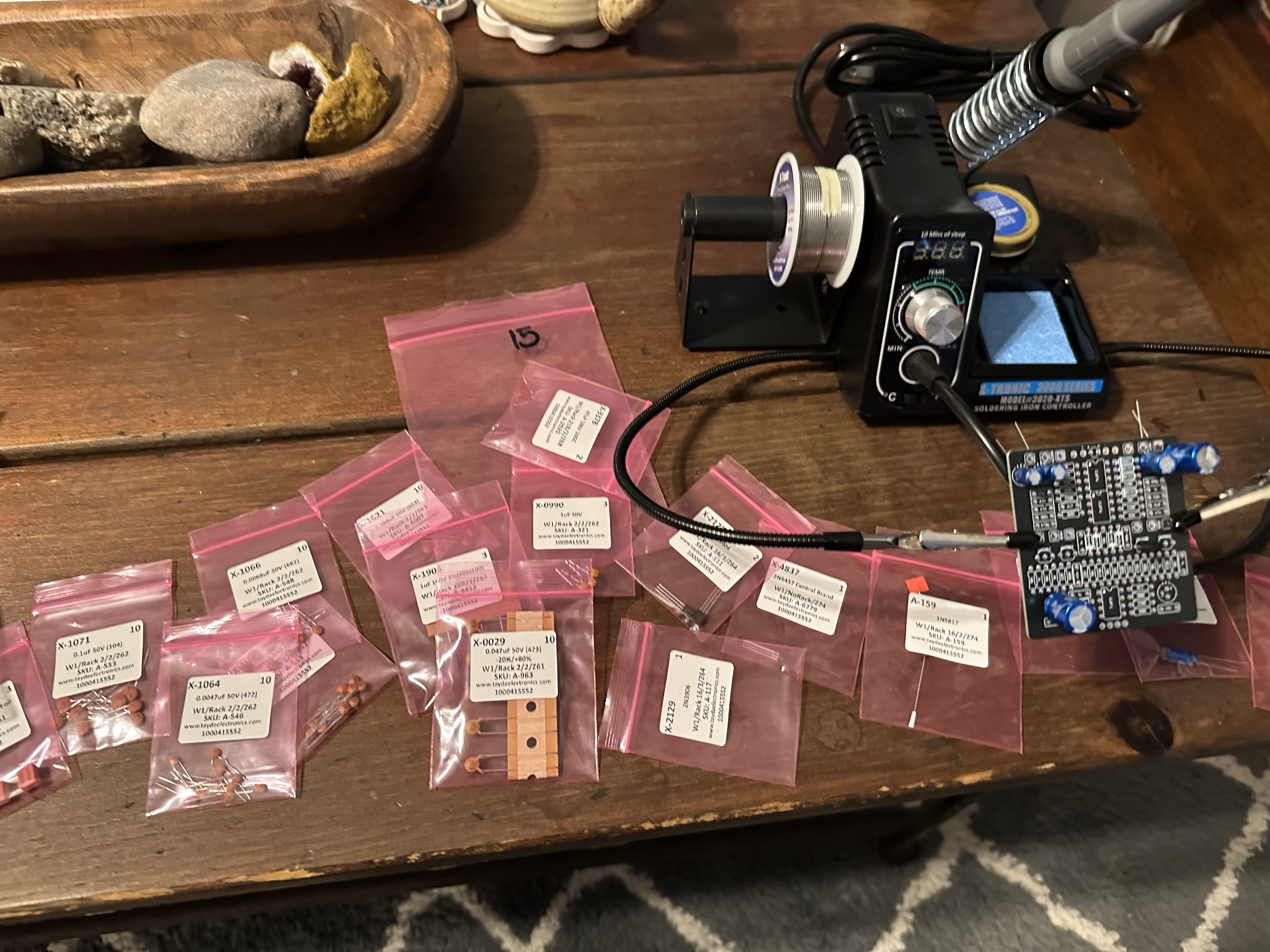
I also treated myself to a new soldering iron. My 12 year old, $10 Radio Shack one takes forever to heat up, then burns everything it touches.
PCB Assembly
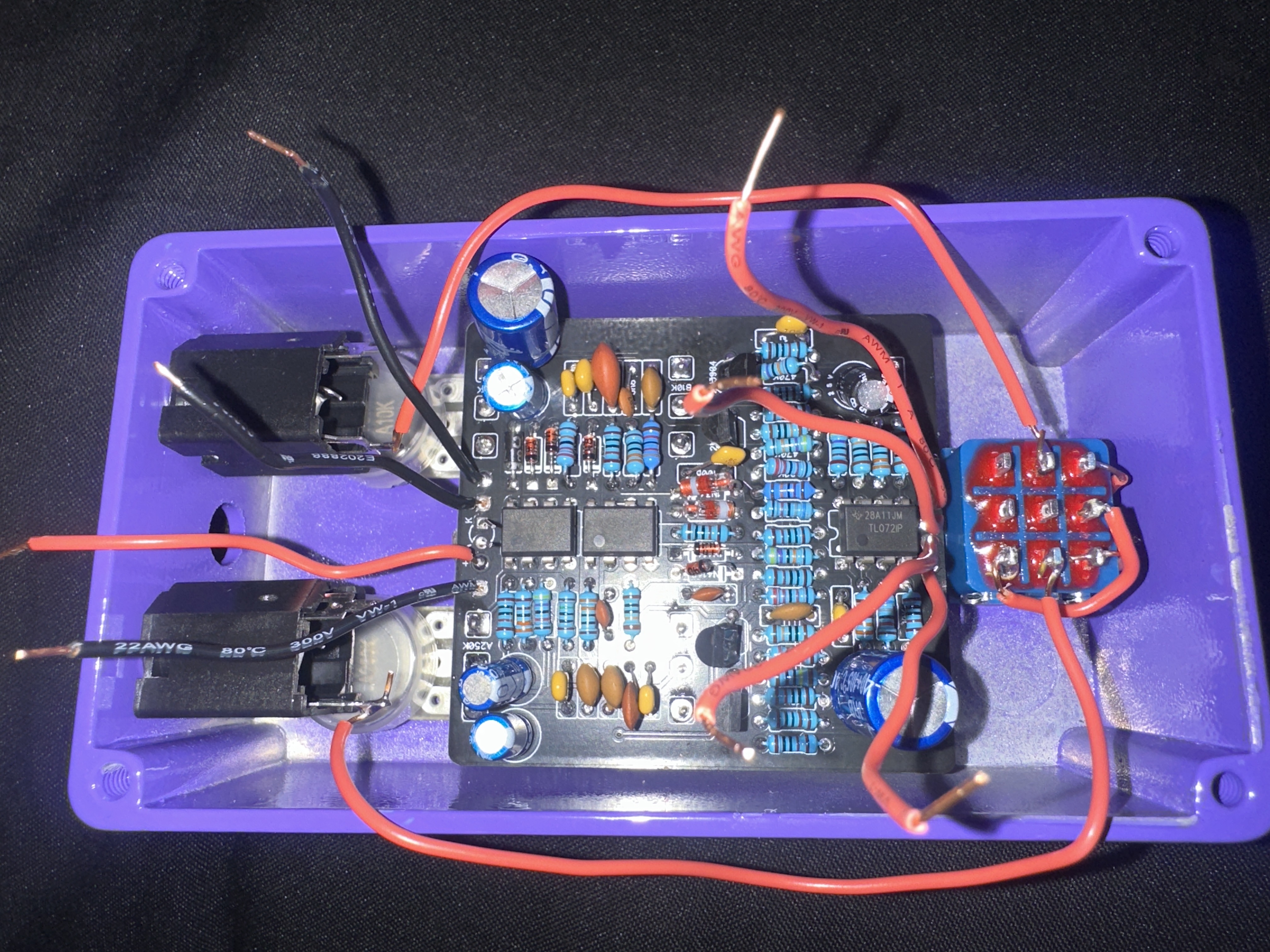
Once I had all of the pieces, I started assembling the parts on the PCB. Pro-tip: bend the leads inwards, not outwards, so they don’t short circuit with their neighbors; that’s the opposite of what you see here.
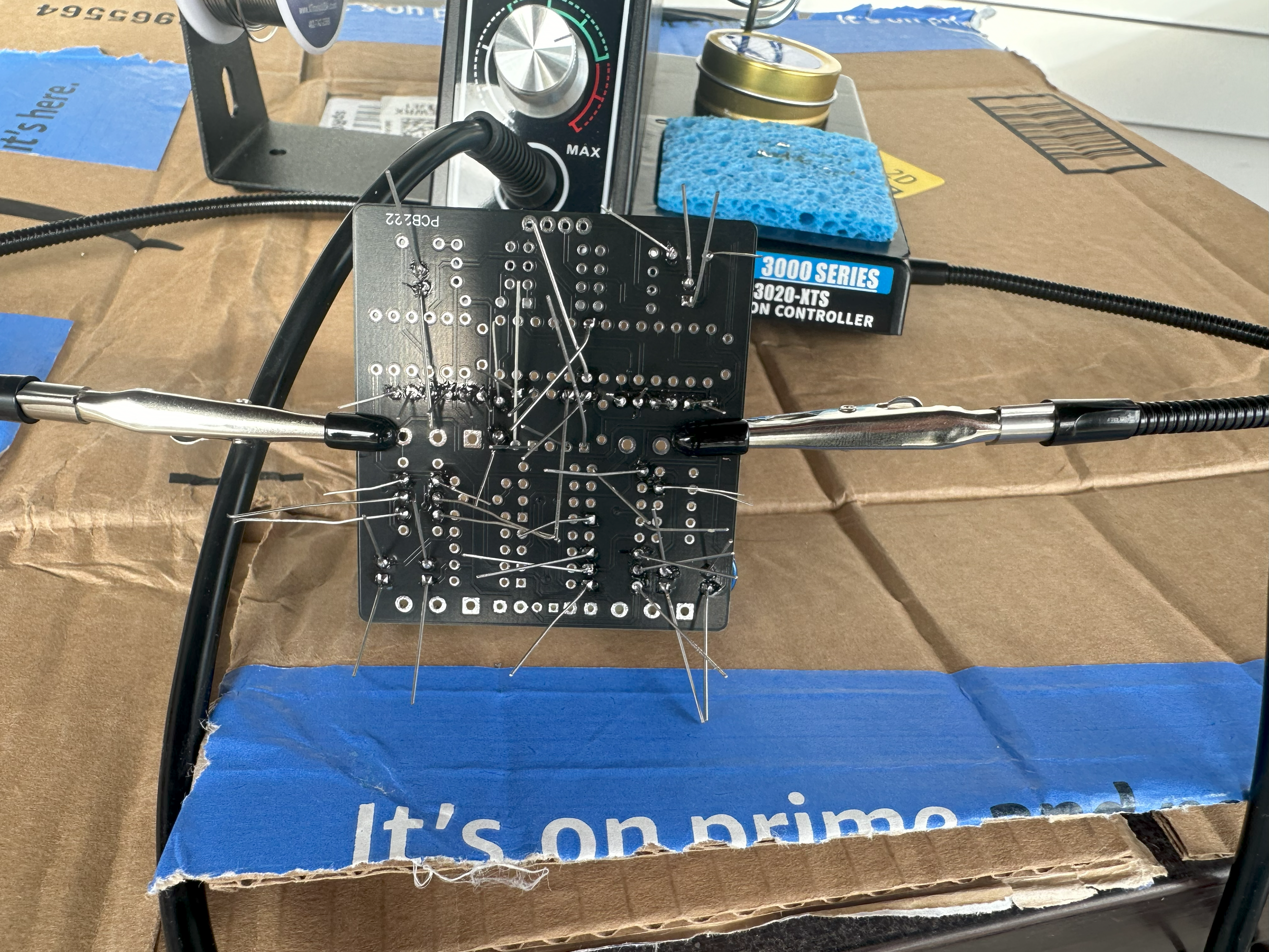
And soldered them.
Unfortunately some of the capacitors I bought had the wrong size; the lead spacing was correct but they were too wide and obstructed access. You’ll see those missing here.
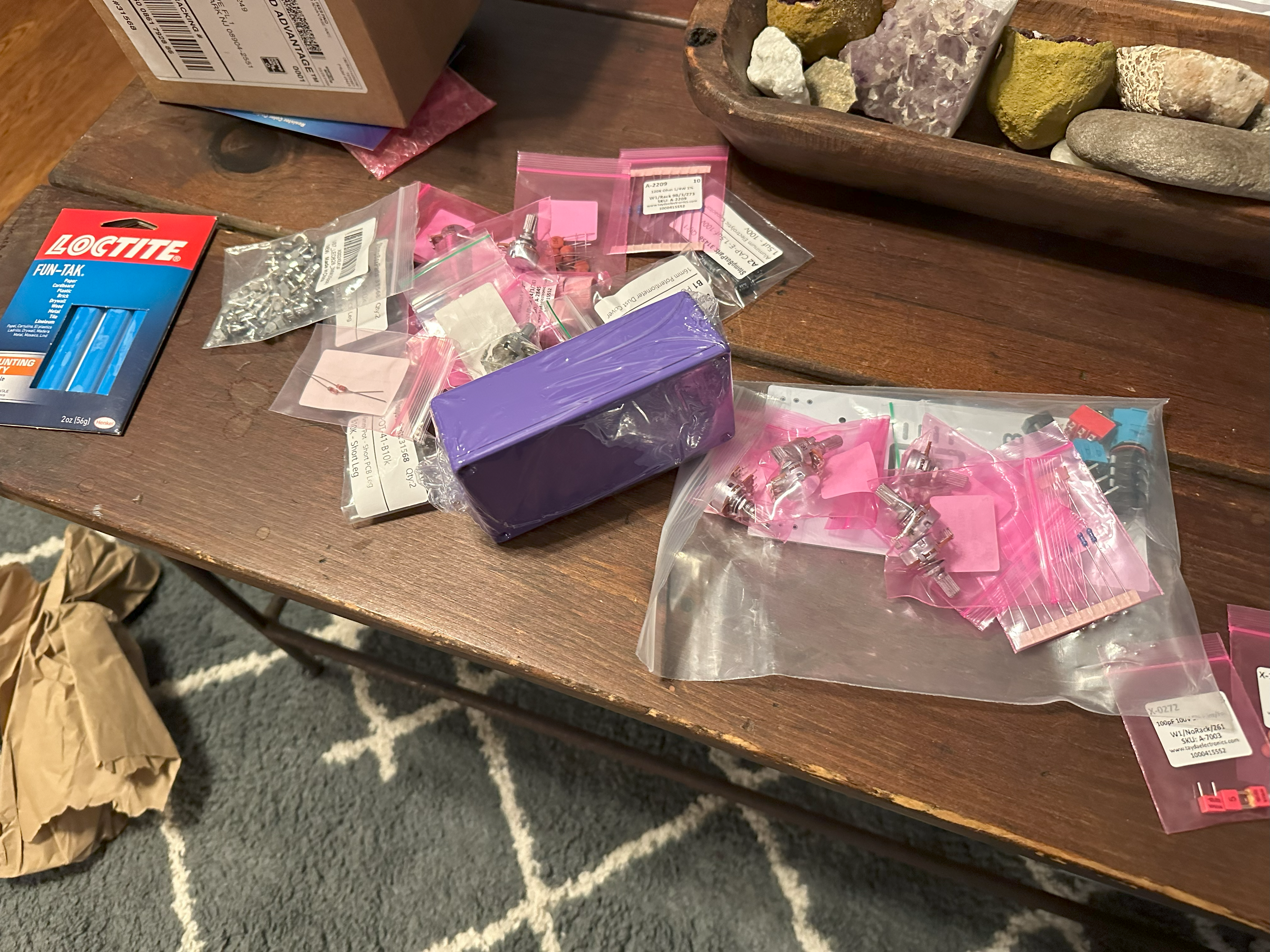
You’ll notice the potentiometers are also missing. Sadly I purchased every type of potentiometers except the one I actually needed. I sent off another order for replacement capacitors and short-leg potentiometers.
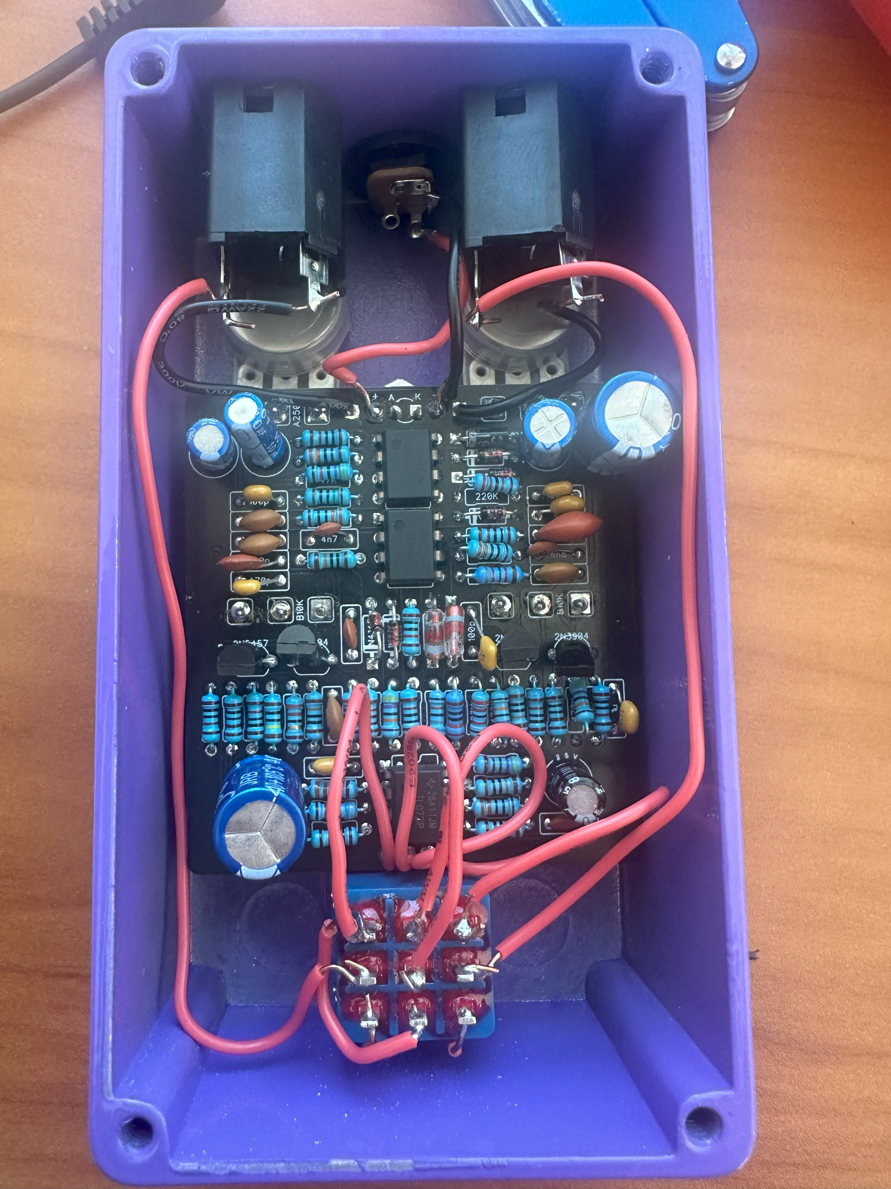
Housing assembly
I dry fit everything to make sure there wouldn’t be any problems getting everything in the housing
Then I alligator clipped everything up and disaster: it sounds like trash!
Diagnostics part 1
I hooked everything up to PedalPCB’s Auditorium testing platform (glad I grabbed one!) to eliminate any problems with the external wiring. Doing so did indeed eliminate any risk that my housing wiring was the issue.
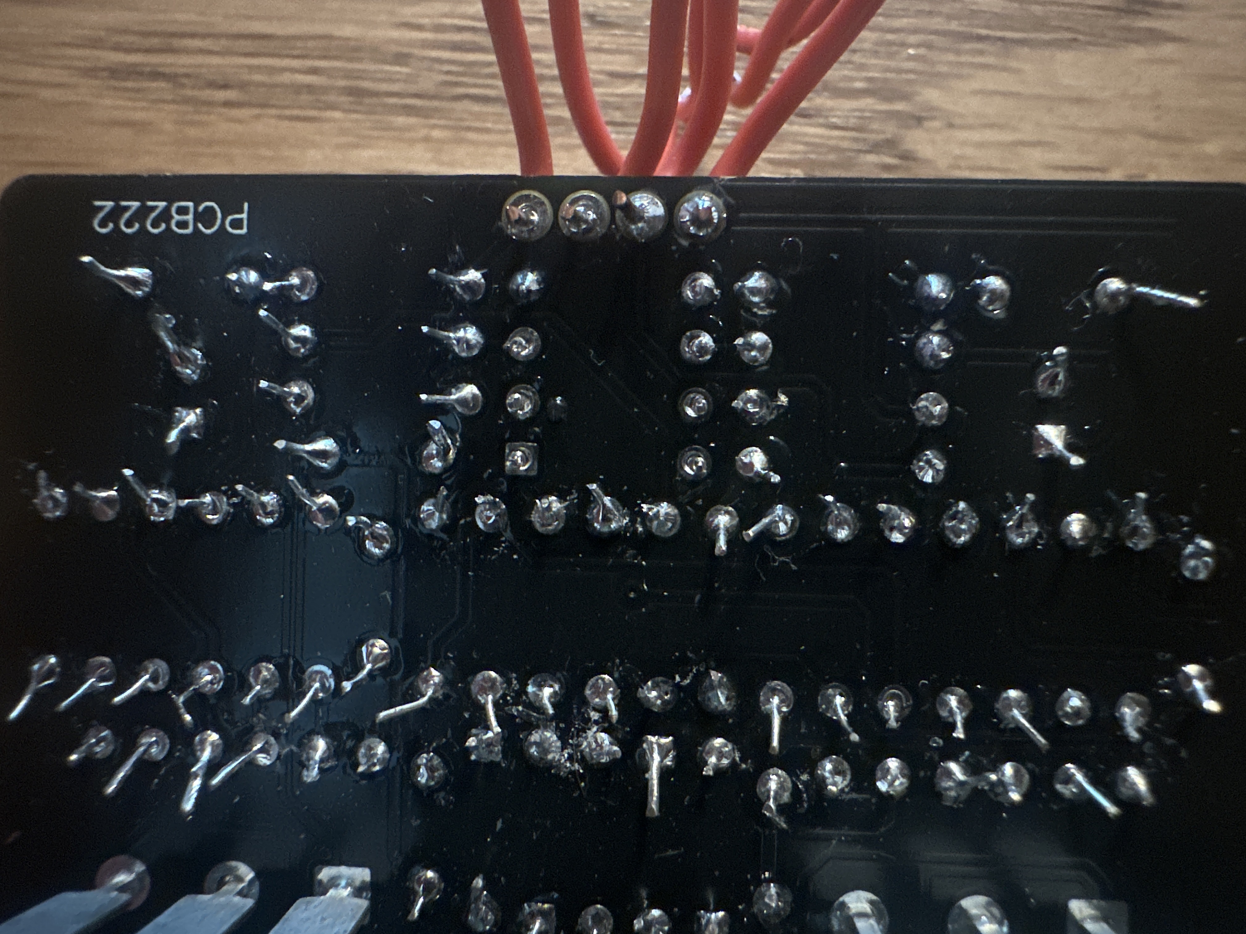
I did a lot of testing. First I touched up these terrible solder joints.
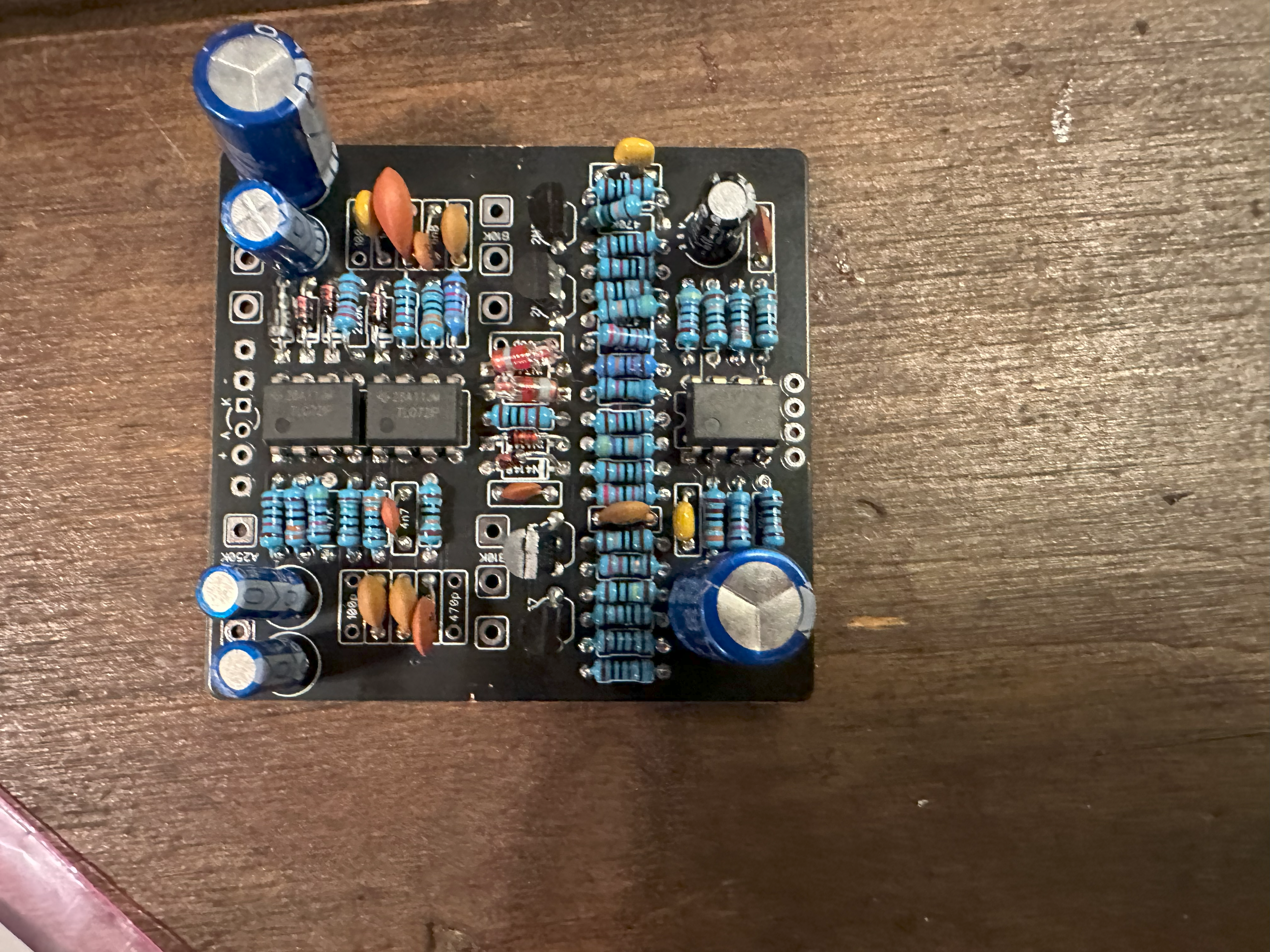
Unfortunately that didn’t solve the problem. Ultimately I went through every single part and checked the values. It turns out that reading resistor and capacitor codings isn’t too difficult and you can get pretty quick at it. Here, at resistor 14, was the problem:
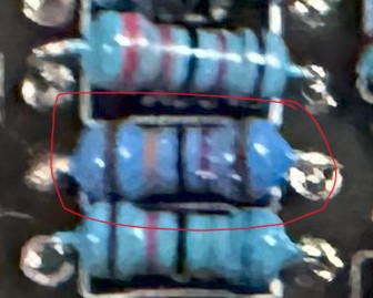
The colors look a bit weird on the camera, but the colors were brown, red, black, orange, brown – a 120 * 1000 = 120k ohm resistor. That’s not consistent with the build docs! Yet another order I sent in to get the correct resistor shipped, and so we wait.
Diagnostics part 2
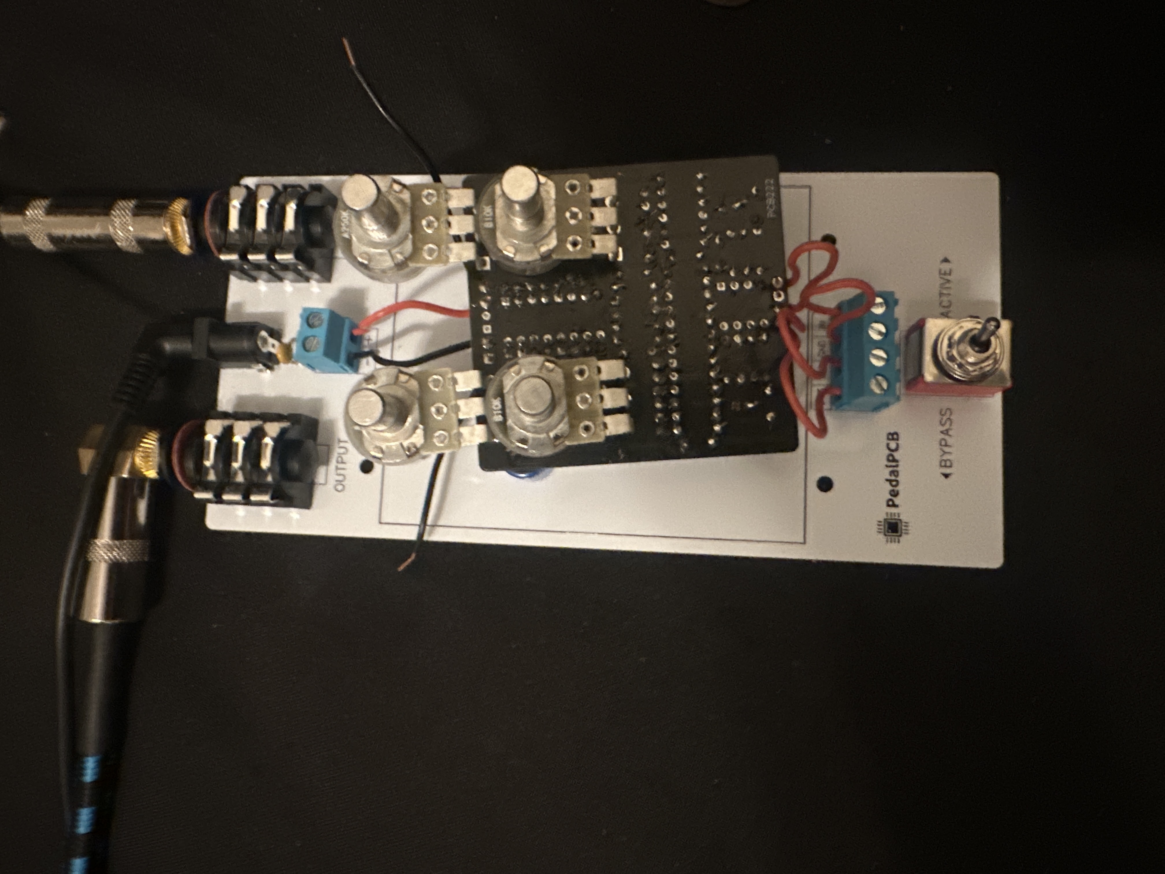
After replacing the bad resistor, I got that sweet, sweet buzzsaw sound out of the pedal Auditorium. It was time to hook it up. I soldered up the external wiring and…
Nothing! What? The LED wouldn’t even turn on. After lots of multimeter shenanigans, I discovered swapping the polarity (positive voltage to the negative terminal) would light up the LED, and then I confirmed this by using a polarity swapping cable and checking the Auditorium’s polarity. Easy fix – just swap the leads coming off the power cable right? Sadly that wasn’t enough; my power jack was grounding the neutral line to the box, so I needed to get a new insulated jack. Yet another shipment required…
Decoration
I created a design for the face in Inkscape, laying out some public domain SVG art and text on top of the drill template
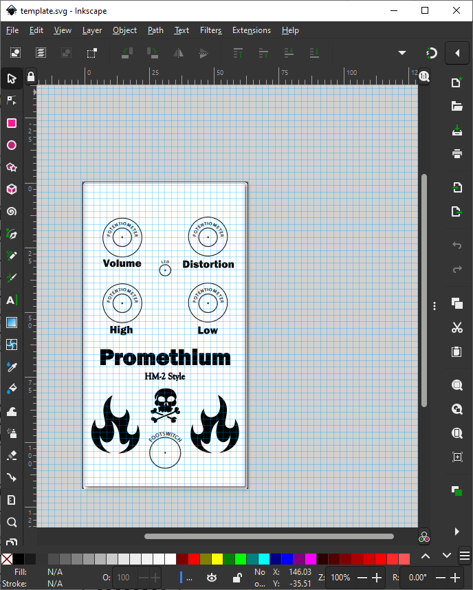
I sent the design off to get printed as a red vinyl sticker. Sadly, it came in all the wrong dimensions. I wonder if something happened with cropping and resizing during format conversion, either on my end or theirs. Either way, I didn’t want to wait another 2 weeks to finish this project, so I went to my local maker space and printed off the vinyl sticker with their help. This turned out to be way more tricky than I expected; I guess $10 wasn’t really such a bad deal after all.
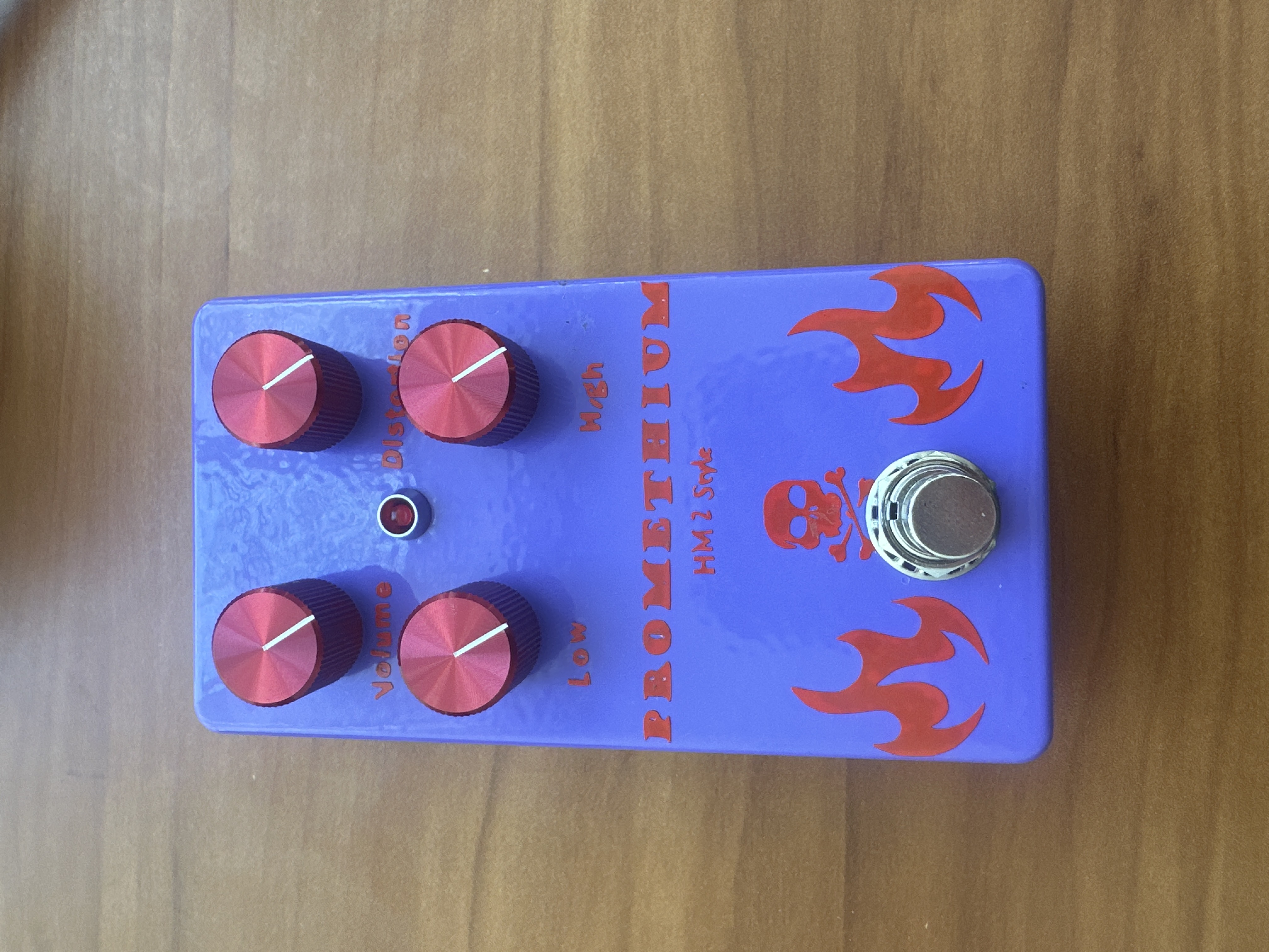
The final product
Everything is done! All that was left was to slap the sticker on, attach the knobs, and close it up.
Lessons
- Measure twice cut once.
- Triple check the measurements. Then check them again.
- Short potentiometer legs is what you want.
- I’m not sure exactly which capacitors I’m supposed to get, but get film ones and check the measurements next time.
- PedalPCB’s polarity is wrong. I’m really glad I didn’t destroy the circuit, and now I know for next time.
Next steps
For housing artwork, I want to explore some other options:
- Tayda offers UV printing, but buying a subscription to Adobe for one print job seems absurd.
- Etching looks interesting. I have a laser printer, so I can do the toner transfer.
- I think my local maker space has a laser cutter, so I could try laser engraving too.
For the next pedal, I’m not sure what I’d do:
- I’d like a reverb of some kind. The FV-1 looks interesting.
- I’d also be curious about chorus or phaser pedals.
- There are some other pedals that could be useful – overdrive or Boost
And, of course, learn some more HM-2 music!